
1 - backfill soil, 2 - expansion cushion, 3 - foundation soil

Pipe and soil interaction methods are based on experimental and theoretical data and is a modified and improved version of [1]. Main points of this methodology are described in "pipe and soil interaction model".
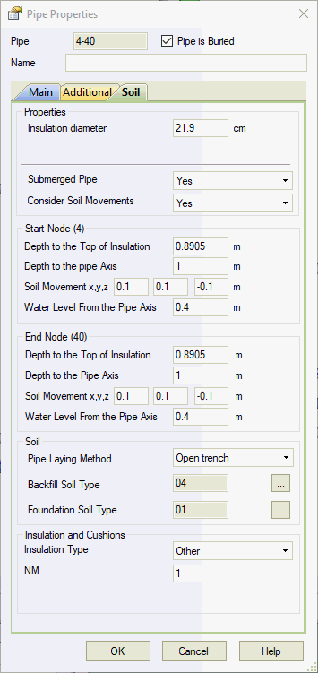
Main and additional element properties for buried elements are input as for standard (above-ground) elements. To take into account soil properties, select "Buried element", after which an additional tab for soil will appear.
Laying depth, water height and subsidence can change along the length of the pipe; therefore, element start and end values are input. Laying depth, water height and subsidence are basically input in nodes, not in elements. Therefore, these values for adjoining elements must be the same in one node. If one value is changed in a node for one element, it will automatically be changed in the same node for the adjoining element.


Property |
Description |
Submerged Pipe |
Toggle on/off consideration of water buoyancy and change in physical and mechanical properties of soil suspended in water |
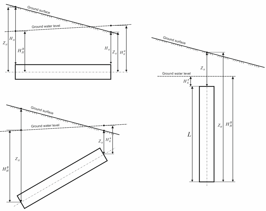
Water height, Hws, Hwe |
Distance from pipe axis to soil
water (in
START-PROF 4.61 and
lower, distance
was calculated from the lowest insulation casing point!).
Height can be negative
or positive. Water
height effects thrust force acting on the pipe (surfacing) and soil resistance to longitudinal and vertical
pipe displacement (soil
properties change in water). More... |
Consider Soil Movements |
Toggle on/off consideration of soil movements. Soil movement allows to model the effects of soil subsidence, frost swelling of soil, landslide, seismic soil movements |
Soil Movement x,y,z |
This feature is used to model soil subsidence (-Z direction), soil frost heave (+Z direction), landslide (any direction X,Y,Z), permanent ground deformation (any direction X,Y,Z), vertical or horizontal seismic fault crossing (any direction X,Y,Z) etc. Soil spring movements in global coordinate system. Soil spring movements can change along the length of the pipe element. Its values is input at the start and end nodes of the pipe element. If soil movement is switched of on neighbor pipe element, then program model variable soil movements from values specified in current pipe to zero values at the end node of connected pipe element.
|
Backfill soil height, Hs, Нe |
Distance between soil surface and the highest insulation casing point. H = Z - (DC / 2). When H is input, Z is calculated automatically, and vice versa. For elements slanted from the horizontal position by more than 10 degrees, backfill height cannot be input. |
Laying depth, Zs, Ze |
Distance from soil surface to
pipe axis.
When H is input, Z is
calculated automatically, and vice versa. |
Backfill soil number1 |
Trench soil number, can be selected from the soil database (see note 1 below). |
Base soil number1 |
Base (undisturbed) soil number, can be selected from the soil database (see note 1 below). |
Pipe laying type |
If open trench type is chosen, then soil natural arch of collapse is not considered. The soil pressure on the pipe is calculated using whole depth. If trenchless type is chosen (for example horizontal directional drilling), then soil natural arch of collapse is considered and soil pressure is calculated using the reduced depth according to the height of natural arch of collapse. Read more...
|
Insulation type2 |
Armopenobeton, polymer, polyurethane, other, no insulation. For polyurethane, insulation casing diameter DC and casing thickness SC are selected automatically from the database based on pipe diameter D. For other insulation types, these data must be input manually |
Insulation casing diameter1, DC |
External insulation casing diameter.
Selected automatically
by pressing If 0 (zero) value specified, then pipe outer diameter is used by default |
Casing wall thickness1, SC |
External insulation casing wall
thickness. Selected
automatically by pressing |
Factor NM |
Factor NM accounting for the difference in the angle of friction of insulation-soil and metal-soil. Depends on external insulation layer material load properties.
Factor is determined according to:
Recommended value for insulation with PE casing is NM=0.67, if insulation is absent NM=1.0 |
Presence of cushions |
Determines whether or not to consider the presence of damping cushions. Please note that using damping cushions does not always increase the allowable axial expansion movement for buried pipelines, and may even reduce its function. Cushions cannot be input for elements slanted from the horizontal position by more than 10 degrees. |
Note 1: When soil selection button is pressed, a dialog window with all soil types from the soils database will be displayed:

To create a new element
first method:
create an above-ground element
select it and
click  on the toolbar
check element
properties (double-click
or use the  toolbar icon)
second method:
create an above-ground element
open the "edit element" dialog window and press CTRL+Enter, after which the "soil" tab will appear
To view properties of an existing element:
Double-click the element in the 3D view
Select the
element and press the  toolbar icon
1. A. Ainbinder, A. Kamershteyn Transmission pipelines stress and stability analysis. Moscow, 1982
2. GOST 30732-2006. Steel pipes and fittings with polyurethane foam insulation in polyethylene casing. Technical conditions. Russian State Committee for Construction. Moscow 2006