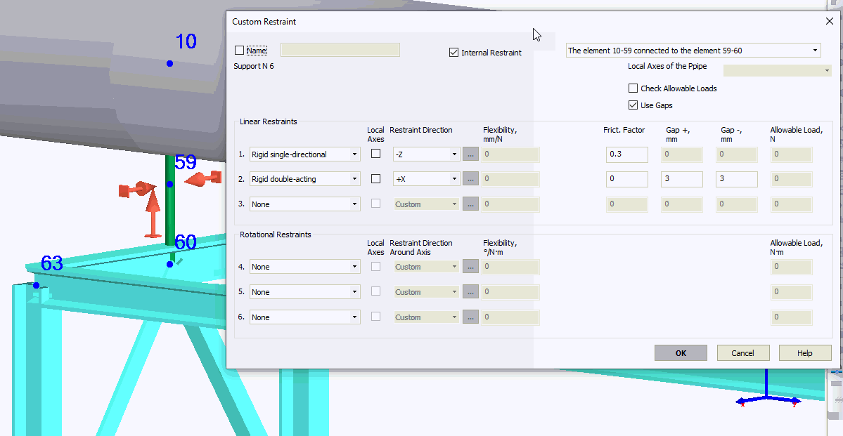
Custom restraints are modeled with any combination of various types of restraints at various angles to restrict displacement and rotation.
Up to a maximum of 3 linear and 3 rotational restraints can be input. The following rotational and linear restraints can be used:
Rigid double-acting (restricts displacement in both directions along its axis)
Rigid single-directional (restricts displacement in one direction along its axis). Restriction direction must be set as +/-
Spring. Flexibility must be input

Property |
Description |
Name |
Element name. If checked then it shown in 3D view |
Pre-compression spring |
There is a pre-compression option for modeling variable spring supports as custom restraints. For slanted variable spring supports, precompression projections are input for global coordinate axes. Positive pre-stretch along an axis creates upward force along this axis, while negative is downward. |
Test state |
In some cases, springs may be temporarily locked during testing, which must be taking into account in the analysis |
Restraint type |
One of 3 types: Rigid double-acting, Rigid single-directional, and Spring. "None" indicates absence of a restraint |
Element local axes |
The local axes of the selected element will be used as restraint local axes Xm, Ym и Zm |
Local axes |
If not checked, allowable loads are set for global coordinate axes (X,Y,Z); if checked, they are for local axes of the adjoining element (Xm,Ym,Zm). All restraints must be mutually perpendicular.
If "other" is selected, any restraint direction can be input
Restraint direction is modeled with three angles between the restraint direction (vector) and global coordinate axes. Minutes are indicates as tenths of a degree (up to two decimal points). For example, 30.25 indicates 30° 15'. For positive angles, "+" need not be written. More...
If the restraints contains at least one single-directional restraint in local coordinates or gaps, the element whose local axes are used as the restraint local axes must be indicated (required for correctly determine the restraint direction). |
Restrain displacement along axis |
Select direction along which displacement is restrained. +/- is irrelevant for double-acting and spring restraints (in the absence of gaps). If gaps are present in double-acting restraints, selecting the positive direction is recommended. For single-directional restraints, +X indicates that displacement in the positive direction of the X axis is restricted, and allowed in the negative. Likewise, -X indicates the opposite. |
Restrain rotation around axis |
Select direction around which rotation is restrained. |
Flexibility |
Spring restraint flexibility |
Rod length |
Restraint rod length, used for considering the pendulum effect (hanger rod displacement from the vertical position). Restraints where rod length is input are considered hangers. If rod length is input, there should be no other linear restraints (the hanger should be the only linear restraint). Rod length and friction factor cannot both be input. |
Friction factor |
Restraint's friction factor. Friction force for this restraint will be taken into account if the restraint is active (for single-directional restraints). If friction factor is input for one of the linear restraints, the total number of restraints should be no more than two (since two or three remaining restraints are used to model friction). Rod length and friction factor cannot both be input. |
Gap +, Gap - |
It is incorrect to add mounting tolerances, used to facilitate installation, as gaps into piping model. Usually there are a lot of such gaps (in each support) and they are very small (1-3 mm). If such gaps are specified in the model the serious problems with iteration convergence may occur. Please remove such small gaps from the model. It is needed to specify only big structural gaps, that are controlled during installation. For example the limit stops, anti-seismic stops etc. Usually such gaps are big (>5 mm) and their number is few. Gap during displacement along and against the restraint direction (if the opposite restraint direction is input, e.g. -X, gaps switch places). Can be input for rigid double-acting and spring restraints. Springs with gaps function as follows: if displacement is less than gap value, the restraint is a spring restraint; if displacement is equal to gap value, the restraint is rigid. |
Internal Restraint |
If checked, then restraint is modeled as internal, connected to another pipe, beam, rigid element, etc. Example. The pipe lies on the resting support, that is connected to the frame made of I-beams. Between the frame (node4) and pipe (node 13) we insert a rigid element. On the rigid element at the distance of half pipe diameter we insert a node 16. In this node we insert the internal restraint that model resting support.
|
Element connected to... |
For internal restraints, it is important which element is connected to other element. For example in this model the guide support is rigidly connected to the element 59-60 and the element 10-59 sliding over it. If we will switch them, then we will have to change the direction of the first restraint from -Z to +Z
It is same as for the two consoles below connected with the resting support. It is important to which (left or right) console the resting support is connected to rigidly. And which console can slide over it
|
Check allowable loads |
If "Check allowable loads" option is checked, START-PROF automatically checks allowable load values against analysis results. If allowable values are exceeded, the corresponding warning is displayed |
Allowable load |
Allowable load in the restraint direction |
For more, see "custom restraints".
For examples, see "custom restraints examples".
To insert an element, select the desired node and use: Insert > Insert Restraint > Custom Restraint
or press the  toolbar
icon.