Tees and stub-ins are a joint of two cylindrical shells and can be of the following types:
Welding Tee Per ASME B16.9 - manufactured by pressing flat steel sheets and welding two halves together
Fabricated Tee - manufactured by factory welding two pipes together
Stub-in - manufactured by on-site welding two pipes together
Custom Tee - the tee with ability to set the custom flexibility factors and stress intensification factors (SIF)
Thermoplastic Tee - GRP or plastic tee
Weldolet - Branch welded-on fitting
Sweepolet - Welded-in contour insert
Extruded Outlet - manufactured by pulling a steel ball through a hole in a pipe
Cross - joint connecting 4 pipe elements
Features of ASME code:
START-PROF doesn't check the wall thickness for tees. For Russian code START-PROF check the wall thickness for all tee types.
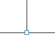
If tee element is not added to a node, the joint is modeled as 3 pipe connection, without rigid element, without flexible hinge and tee stress is not calculated.

Fig. 1. Modeling a intersection of two pipes without a tee
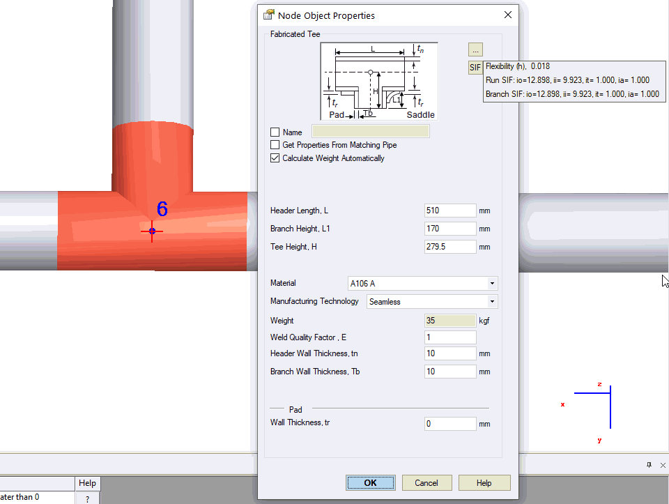
If any type of tee is added into the intersection node, then you can specify tee length (L), tee height (H), header wall thickness, and branch wall thickness.
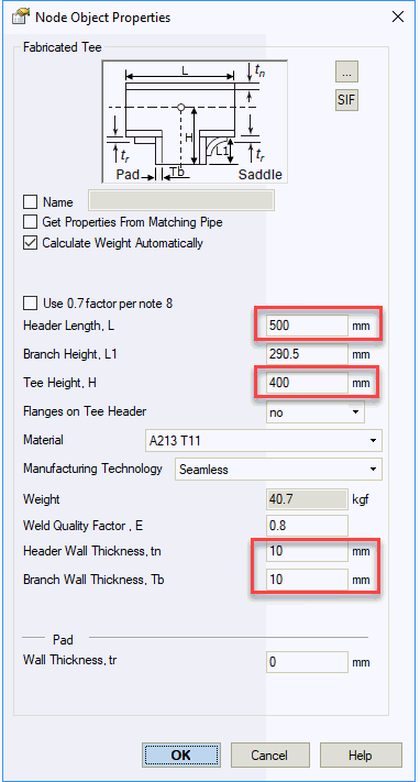
If you don't specify tee length (L) and tee height (H) then only rigid element 10-20 (H=Dh/2, Dh – header outer diameter) inserted. Weight of rigid element, fluid and insulation is zero
When you run analysis simple tee model is automatically replaced by complex model. Added 6 additional nodes (21, 2, 3, 4, 5, 20). Nodes are hidden for user. It is visible only in developer mode.
10-20 Element is rigid (H=Dh/2, Dh – header outer diameter). Weight of rigid element, fluid and insulation is zero
4-10 and 10-5 elements length is 1 mm (L=2mm)
20-21 pipe element has a wall thickness specified in “Tee” dialog box Tb=10 mm. It can be thicker than the connected pipe
4-3 & 5-2 pipe elements has a wall thickness specified in “Tee” dialog box tn=10 mm. It can be thicker than the connected pipes
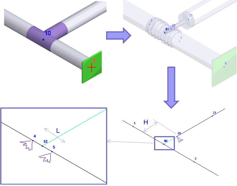
This is the tee object model that you see in START-PROF:
And this is the real tee model, that is used inside the software. The header and branch pipes have a different wall thickness than the connected pipes. The special flexible springs are added to model the header (2) or branch (1) flexibility if ASME B31J is used. The rigid element always used to remove the "dummy" flexibility of the branch element (3)
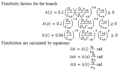
For “Custom Tee” and for any standard tee if ASME B31J code selected, additional run flexibilities added into nodes 4 & 5, and branch flexibilities added into node 20. Flexibilities calculated according to ASME B31J
If “Consider Tee Branch Flexibility” option selected, then 4 & 5 nodes are not created for standard tees. The flexibilities in node 20 calculated according to the standard selected in Project Settings. For ASME and DL/T 5366-2014 the standard is ASME BPV SIII div 1 class 1 NB 3686, flexibility is considered for reducing tees with Db/Dh<0.5. For Russian codes flexibility is considered for reducing tees with Db/Dh<0.8.
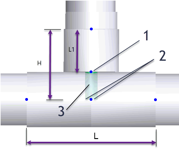
Tee weight Q is distributed along the header pipe L, q=(Q-qp*L1)/L, qp - pipe connected to branch weight, L1=H-D/2 - branch length. The rigid element length is zero. The weight of pipes covered by tee is removed. The insulation and product weight is the same as on connected pipes. Snow, ice, wind, and user defined uniform loads are got from connected pipes.
Stress in tees is calculating taking into account concentration (intensification) factors, which indicate to what degree these stresses exceed bending stress in branch or header cross-sections without weakness caused by the stub-in. Formulas for calculating the intensification factor are given in standards. Equivalent stress is calculated for three tee cross-sections 1, 2, 3 (fig. 3). The greater value is used in analysis.

1 - hidden, automatically added node
Fig. 3. Tee cross-sections (1,2,3) for stress analysis
To insert an element, select the desired node and use: Insert > Insert Tee
To view properties of an existing element:
Double-click the element in the 3D view
Select the
element and press the  toolbar icon