
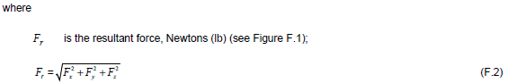
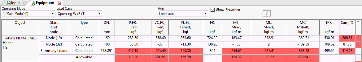
This table displays nozzle and equipment loads. Table view and contents depend on four properties Operating modes, Submode, Occasional loads. Information about it can be found in Restraint Loads table. See also "How to Reduce the Nozzle Loads in START-PROF"
Topics:
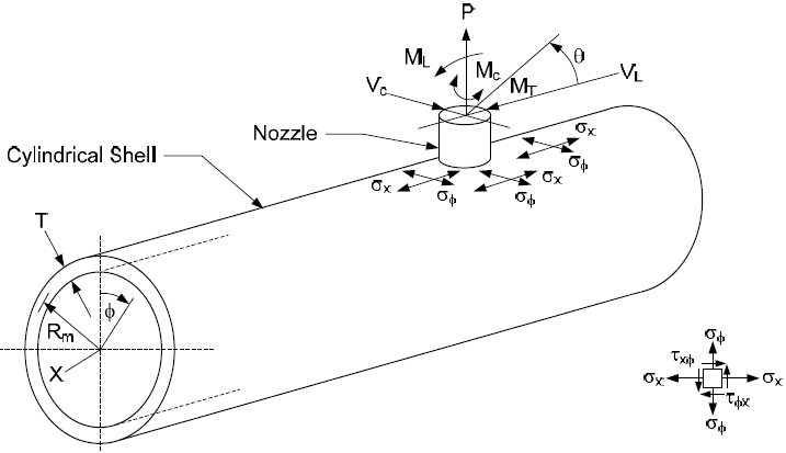
The following axes are used in this table:
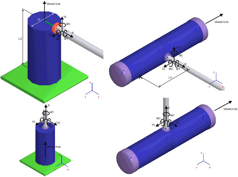
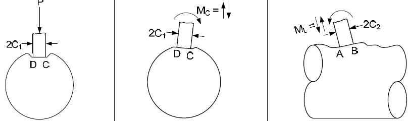
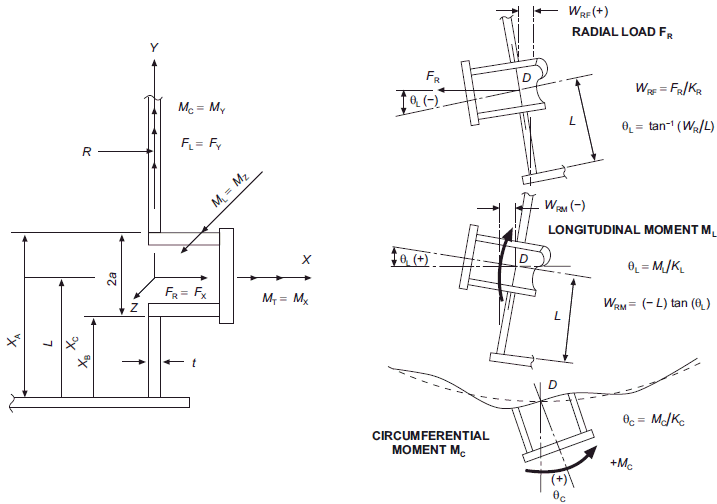
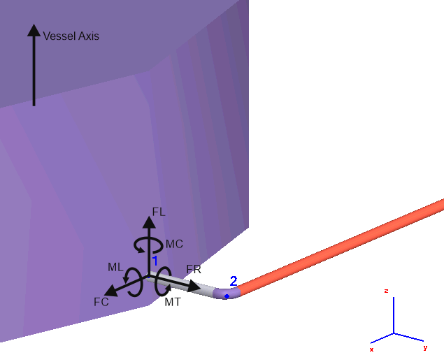
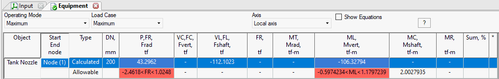
P - along nozzle axis
VC - perpendicular to nozzle axis and perpendicular to the vessel axis
VL - perpendicular to nozzle axis and along the vessel axis
MT - Torsion (around nozzle axis)
ML - in plane of nozzle and vessel axes
MC - out-of-plane of nozzle and vessel axes
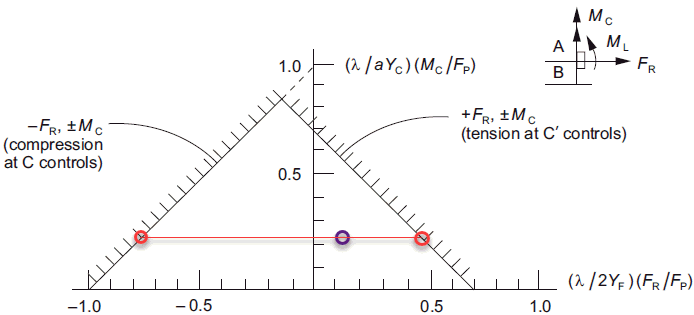
If allowable loads option "Manually" chosen, then nozzle loads are printed and corresponding allowable load values are printed on the second row
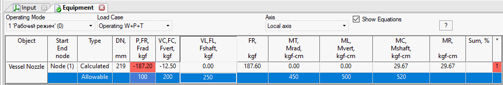
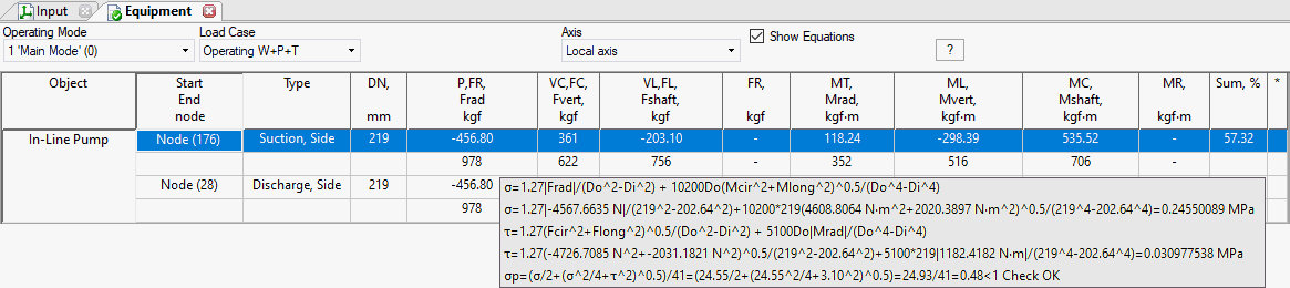
If allowable loads option "Stress check by WRC 107/537/297" chosen, then in cell "Sum" printed the greatest stress to allowable stress ratio. And also if you move mouse over the loads row, the detailed stress calculation report are printed according to WRC 107/537/297
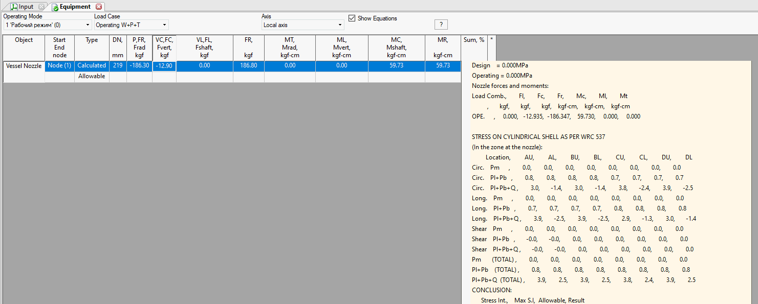
Axes: FR=FX, FC=FZ, FL=FY, MT=MX, ML=MZ, MC=MY
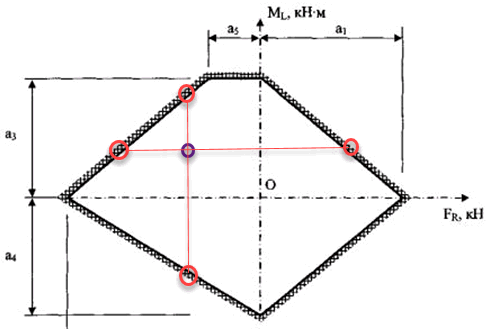
If option API 650 was chosen, the FR, ML, MC loads are printed and corresponding allowable loads or range of allowable loads.
If option STO SA 93-002-2009 was chosen, the FR, ML, MC loads are printed and corresponding allowable loads or range of allowable loads.
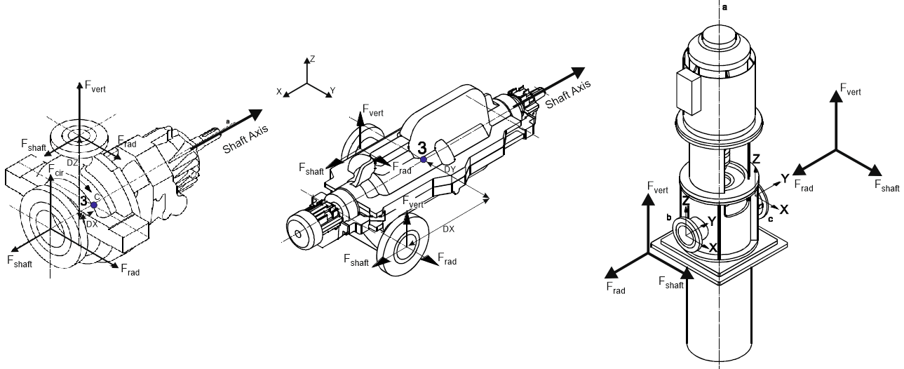
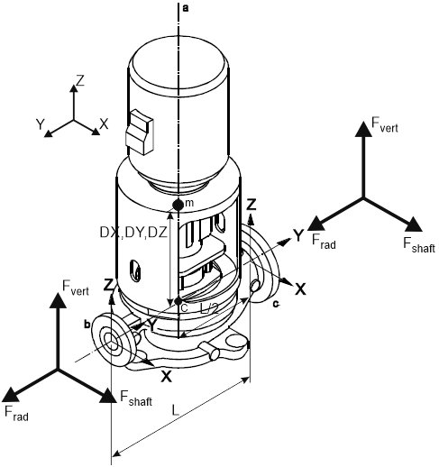
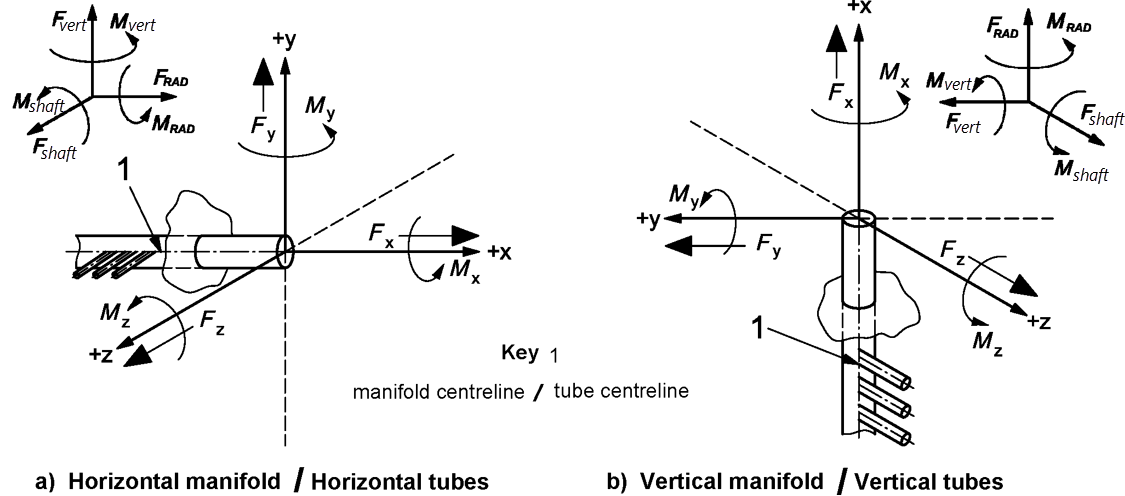
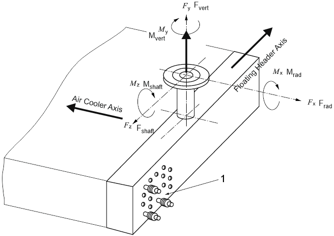
Axes: Frad=FY, Fvert=FZ, Fshaft=FX, Mrad=MY, Mvert=MZ, Mshaft=MX
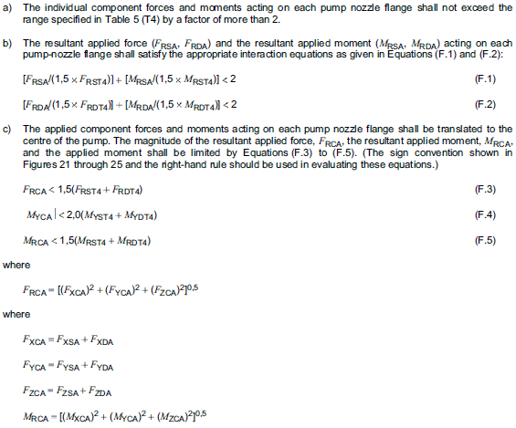
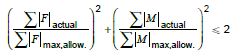
For each nozzle in the first row printed loads, in the second row allowable loads from the table 5, multiplied by "Manufacturer Allowable Multiplier" (default value 2.0). In "FR" cell of the first row value of FRSA/FRDA, in the second row FRST4/FRDT4. In "MR" cell of the first row value of MRSA/MRDA, in the second row MRST4/MRDT4. In "Sum" field the ratio of the left to the right side of the equations F.1 and F.2 are displayed.
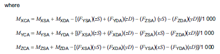
In the first row of "summary loads" the FXCA, FYCA, FZCA, FRCA, MXCA, MYCA, MZCA, MRCA values are displayed. In the second row in "FR" field the ratio of the left to the right side of the equations F.3 is displayed. In "MR" field the ratio of the left to the right side of the equations F.5 is displayed. In "Mrad" field the ratio of the left to the right side of the equations F.4 is displayed.
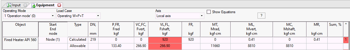
Axes: Frad=FY, Fvert=FZ, Fshaft=FX, Mrad=MY, Mvert=MZ, Mshaft=MX
For each nozzle in the first row printed loads, in the second row allowable loads, multiplied by "Manufacturer Allowable Multiplier" (default value 1.4). In "Sum" field is displayed the ratio of the left to the right side of the equation
Same as ISO 9905
Same as ISO 9905
Axes: Frad=FY, Fvert=FZ, Fshaft=FX, Mrad=MY, Mvert=MZ, Mshaft=MX
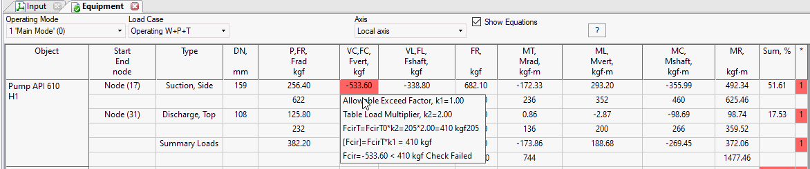
API 610: For each nozzle in the first row printed loads, in the second row allowable loads for side nozzle, multiplied by "Table Nozzle Loading Factor" (default value 2.0). In "Sum" field is displayed the ratio of the left to the right side of the equation F.6.
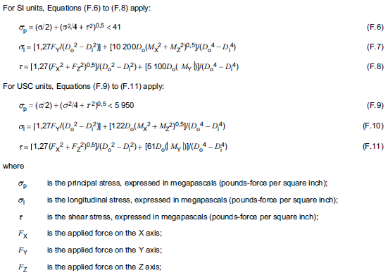
ISO 9905, ISO 5199, Other: For each nozzle in the first row printed loads, in the second row allowable loads for vertical pumps, multiplied by "Manufacturer Allowable Multiplier" (default value 1.4), multiplied by ratio of elastic modulus in hot and cold state and modified according to pump type. In "Sum" field is displayed the ratio of the left to the right side of the equation:
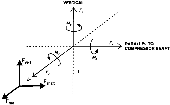
Axes: Frad=FZ, Fvert=FY, Fshaft=FX, Mrad=MZ, Mvert=MY, Mshaft=MX
Flong axis is always goes along shaft axis. Fcir axis is always vertical.
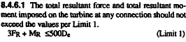
In the row for the each nozzle the nozzle loads are displayed. In "Sum" field is displayed the ratio of the left to the right side of the equation F.1a/F.1b, multiplied by "Factor for Allowable Loads":
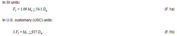
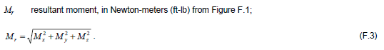
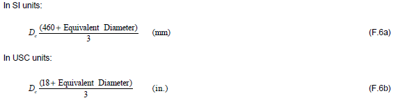
In the field "DN" the equivalent diameter is displayed:
In "Summary Loads" in the first row displayed the summary loads on compressor, in the second row the allowable loads, multiplied by "Factor for Allowable Loads" is displayed.
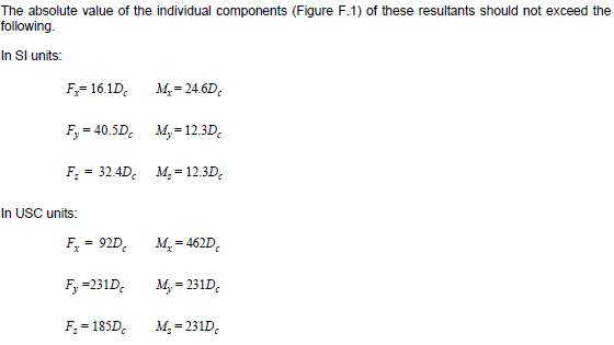
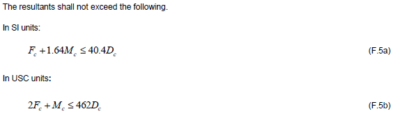
In "Sum" field is displayed the ratio of the left to the right side of the equation F.5a/F.5b, multiplied by "Factor for Allowable Loads":
In the field "DN" the equivalent diameter is displayed:
The same as API 617, but allowable loads are 1.85 times lower:

Axes: Frad=FX, Fvert=FY, Fshaft=FZ, Mrad=MX, Mvert=MY, Mshaft=MZ
In the first row the load values are displayed. In the second row the allowable values are displayed.
Axes: Frad=FX, Fvert=FY, Fshaft=FZ, Mrad=MX, Mvert=MY, Mshaft=MZ
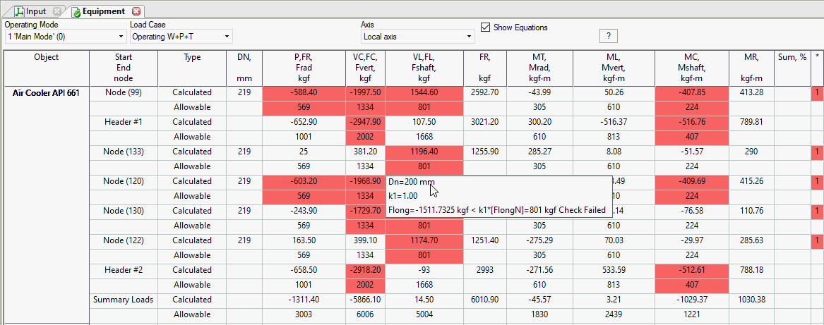
For each nozzle in the first row displayed the loads on the nozzle, in the second row the allowable loads from table 4, multiplied by "Factor for Nozzle Allowables" (default 1.0).
For each floating header in the first row displayed the summary loads on the floating header from all connected nozzles, in the second row the allowable loads according to 7.1.10.2, multiplied by "Factor for Floating Header Allowables" (default 1.0).
For whole heat exchanger in the first row displayed the summary loads on the whole heat exchanger from all connected nozzles, in the second row the allowable loads according to 7.1.10.2, multiplied by "Factor for whole Heat Exchanger Allowables" (default 3.0 according to 7.1.10.3).
After analysis: Output > Restraint and Equipment Load