Read about START-PROF pipe stress analysis software
START-PROF can estimate the support loads and stresses caused by relief valve discharge by static method.
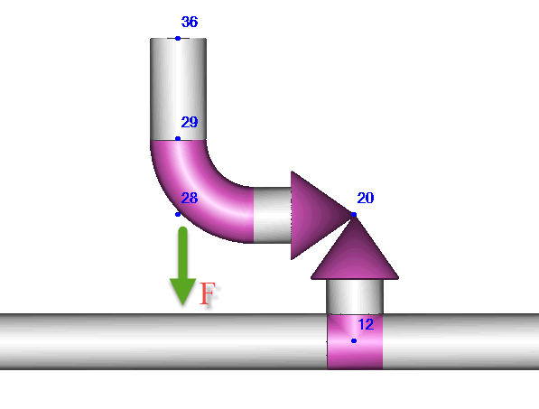
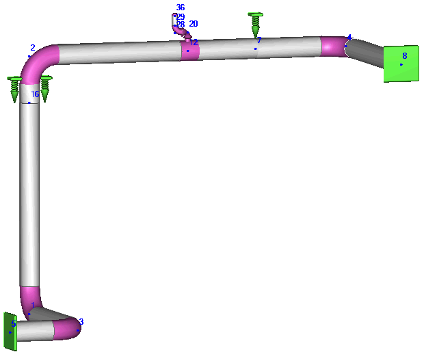
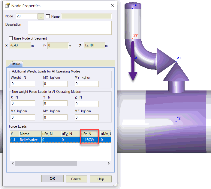
The relief valve discharge thrust load acts on elbow 28. In START-PROF it should be applied at the end of the elbow in 29 node.
There's a several methods to estimate the dynamic equivalent thrust force F:
Equivalent dynamic thrust force can be estimated by equation:
F = DLF ∙ F1
where
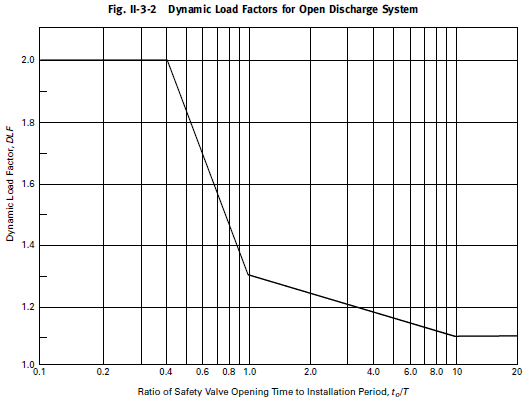
DLF - dynamic load factor, depend on first natural period of piping. If period is unknown the DLF=2.0.
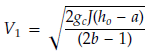
F1 - static reaction force, N. May be computed by the following equation:
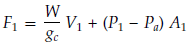
where
W - mass flow rate (relieving capacity stamped on the valve by 1.11), kg/sec
gc=1 - gravitational constant,
Pa - atmospheric pressure, N/m²
A1 - exit flow area, m² A1=p∙(D-2t)²/4
V1 - exit velocity (node 36), m/sec
P1 - static pressure, N/m²
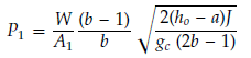
h0 - stagnation enthalpy at the safety valve inlet, MJ/kg
J = 999835.0529 m*N/MJ
a, b - constants according to table below
Steam Condition |
a, MJ/kg |
b |
Wet steam <90% quality |
0.6769 |
11 |
Saturated steam ≥90% quality 1.05 kgf/sm² ≤ P1 ≤ 70.31 kgf/sm² |
1.9143 |
4.33 |
Superheated steam ≥90% quality 0.07 kgf/sm² ≤ P1 ≤ 140.61 kgf/sm² |
1.93291 |
4.33 |
Example project file: ReliefValve.ctp
Input data:
Diameter of discharge pipe: 0.219 m
Wall thickness of discharge pipe: 0.016 m
product: Saturated steam
relief valve relieving capacity: 48 kg/sec
Steam pressure: 64 kgf/sm²
Steam temperature: 538°C
Calculation:
A1=p∙(D-2t)²/4 = 3.14159∙(0.219-2∙0.016)²/4 = 0.027465 m²
a = 1.9143 MJ/kg
b = 4.33
W = 48∙1.11 = 53.28 kg/sec
stagnation enthalpy for steam at 64 kgf/sm² and 538°C h0 = 3.506 MJ/kg
J = 999835.0529 m*N/MJ
P1=53.28/0.027465*(4.33-1)/4.33*(2*(3.506-1.9143)*999835.0529/(2*4.33-1)/1)^0.5 = 961693 N/m²
V1 = (2*999835.0529*(3.506-1.9143)/(2*4.33-1))^0.5 = 644.6 m/sec
F1 = 53.28*644.77 + (961693-100000)*0.027465 = 58019 N
F = DLF ∙ F1 = 2*58019 = 116039 N
Create additional occasional force loading 1.1 in operation mode editor:
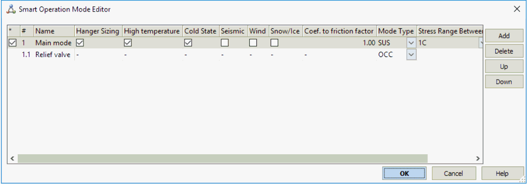
If we have more relief valves, then we should add more additional modes (1.2, 1.3, etc.) if it's open not simultaneously.
Apply dynamic thrust force at node 29 for mode 1.1:
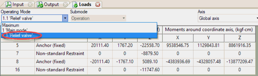
Support loads due to relief valve thrust load:
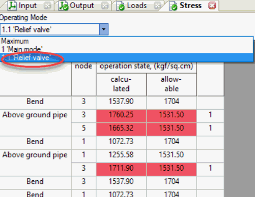
Stresses due to relief valve thrust load: