Bends (welded or made with pipe bending) allows a change in the piping axis direction. START-PROF takes into account the increased flexibility of bends and runs a stress analysis. Adjoining straight pipes prevent ovalization of the bend cross-section, increasing the bend's bending stiffness. There are several bend types:
Forged elbow - manufactured by passing a heated pipe through a horn-shaped core
Induction bend - manufactured with hot or cold pipe bending
Miter bend (closely spaced) - welded from several short pipe sections
Welding elbow - manufactured by pressing flat steel sheets and welding two halves together
Large radius bend - pipeline large radius bend manufactured using hot or cold method, usually R>10DN
Elastic bend - pipeline Natural Bend. Elastically bent pipe section with a large radius, usually R>1000DN. Unlike an ordinary large radius bend big radius bend, an elastic bend has initial stress and bending moments
Miter joint (widely spaced miter bend) - single miter joint that is used for modelling the widely spaced miter bends of as standalone element
Custom bend - the bend with ability to set the custom flexibility factors (k-factors) and stress intensification factors (SIF)
Features of ASME code:
There's no difference in stress analysis of Forged elbow, Induction bend and Welding elbow in ASME and EN codes. But these bends are calculated by different methods in GOST and SP codes. To save the piping models compatibility user can specify different bend types for ASME code too
START-PROF check the wall thickness for Induction bend and Miter bend (closely spaced). For other bend types the wall thickness is not checked. For Russian code START-PROF check the wall thickness of all bend types.
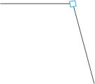
If there is no bend in a node, the connection between pipes is represented as an intersection of two pipes, rigidly connected each to other (without taking into account the bend flexibility), and stresses in adjoining elements are calculating without taking into account the stress intensification factors (fig. 1).

Fig. 1. Connection without a bend
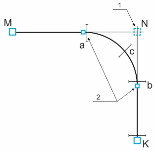
If the bend is inserted into the node A, then nodes B and C are automatically added at the intersection of bend radius and adjoining pipes (fig. 1, a). Bends are modeled as curved rods (fig. 2, a), taking into account the Karman's effect - increased flexibility due to cross-section ovalization during bending (fig. 2, b) based on standards selected in Project Settings. Stress analysis is performed using thin casing analysis theories and according to standards selected in Project Settings. Bend weight is modeled as uniform load along the arc length. The weight of straight pipe parts that covered by bend is removed. The insulation weight, fluid weight, snow, ice, wind, and user defined uniform loads are got as average value from two connected pipes and modeled as uniform load along the curved rod. Angle used for calculation of wind load are taken as angle between wind direction and bend chord (B-C).
Bends cannot have a central angle of more than 180°

Fig. 2. Modeling bends
Equivalent stress is calculated for 3 or more cross sections: a, b, c, ... (fig. 3). The largest of the two values is taken. For long radius bends the number of cross sections is greater than 3.

Fig. 3. Cross sections for stress analysis
1 - dummy node visible to user, 2 - automatically added nodes invisible to user
To insert a bend, select the desired node and use the menu option: Insert > Insert Bend
To view properties of an existing element:
Double-click the element in the 3D view
Select the
element and press the  Toolbar icon