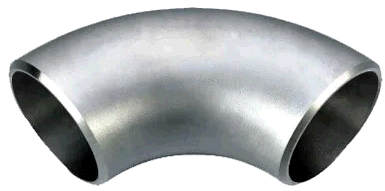
This bend is produced without using of longitudinal welds like welding elbow. There's no difference in stress analysis of Forged elbow, Induction bend and Welding elbow in ASME and EN codes.
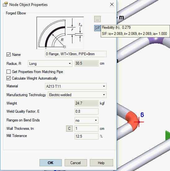
Central bend angle should not exceed 90 degrees (More...). START-PROF doesn't check the Wall thickness for this type of bend according to ASME code, but check it according to Russian codes.
Property |
Description |
Name |
Element name. If checked then it shown in 3D view |
SIF |
If you push this button, you will see h, SIF, k-factors for the bend |
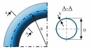
Radius, R |
Bend average radius (0.5D<R<10D). Long - 1.5DN, short - 1.0DN |
Get properties from matching pipe |
Get properties from matching pipe |
Calculate weight automatically |
If selected, reducer weight is calculated automatically as torus volume with wall thickness equal to that of adjoining pipes |
Weight |
Bend weight (with flanges) without insulation and product. Set according to standards without taking into account the overload factor. Product and insulation weight with corresponding overload factors are calculated automatically based on adjoining pipes |
Longitudinal Weld Joint Efficiency Factor, E |
Longitudinal weld joint efficiency factor, E. More... |
Calculate angle automatically |
The bend angle used in bend's flexibility factor (k-factor) calculation in some codes. The option "сalculate angle automatically" should be turned on by default. It is recommended to turn off this option when the bend was splitted into several parts to model the support on bend. In this case the angle should be specified for full bend, not for each part of bend |
Angle |
|
Manufacturing technology |
For ASME B31.1, ASME B31.3, DL/T 5366-2014 seamless pipe will always use Wl=1.0. For electric-welded pipe Wl will be specified from database. More... When using GOST 32388-2013, pipe physical properties are taken from different materials databases depending on pipe type (seamless/welded). |
Material |
Material from materials database |
Presence of flanges |
Number of flanges must be selected. Flanges are rigid elements and prevent cross-section ovalization. Flanges affect the flexibility factor and stress intensification factor.
|
Position of welds |
Position of welds: in the bend plane, in the plane perpendicular to the bend plane. See fig. 1 |
Nominal wall thickness, S |
Nominal (actual) wall thickness |
Mill tolerance, С1 |
Mill tolerance at the time of production. More... When analyzing based on RD 10-249-98 (section 3.3.2.8), 3 mill tolerance values must be input (С1=С11+С12): external, neutral and internal bend section, with a difference equal to the value of С12. More... |
Corrosion and wear allowance, С2 |
Corrosion and wear allowance (working mill tolerance) for wall thickness. More... |
Do not check internal bend wall thickness |
According to RD
10-249-98 section
3.3.2.8 "for extruded
elbows manufactured in a closed press, or
for bends manufactured on machinery with high-frequency currents and axial preload, c12 к sR1
allowance must be from
0.05s to 0.1s.
c12 к sR3
allowance is 0, and internal
bend analysis is not performed. |
Hand-lay |
Selected if elbow is manufactured with manual winding |
Stress correlation along two axes, r |
Based on ISO 14692 section 7.10
|
Qualified stress, qs |
If this field is blank then qs is got from material database Based on ISO 14692 section 7.8
|
Internal protective layer thickness |
|
External protective layer thickness |
|
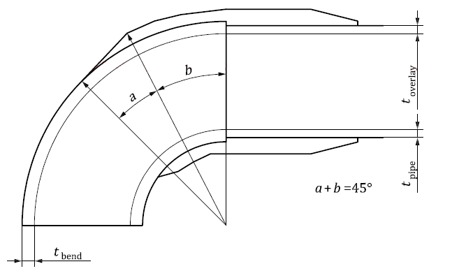
Angle of end thickness |
Angle suntended by overlap length of lamination, b
|
Refresh SIF and k using FEA |
|
SIF |
To insert a bend, select the desired node and use the menu option: Insert > Insert Bend > Forged Elbow
To view properties of an existing element:
Double-click the element in the 3D view
Select the
element and press the  toolbar icon