This table displays all piping model node displacements. Table view and contents depend on four properties, which must be input:
Property |
Description |
Operating Mode |
Choose operation mode for which the results will be displayed
Maximum - the maximum value will be displayed in every cell from all operation modes Here you can see analysis results from each of additional force-based loading, seismic, wind, and ice loading |
Submode |
For every operating mode software calculates several submodes (piping states)
For more information, see force and effect combination. |
Occasional Loads |
|
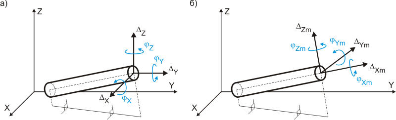
Axis |
Linear and rotational displacements are displayed as projections on coordinate axes:
Fig. 1. Node displacement in global (general) and local coordinate systems |
Displacement filter |
Only linear, only rotational, or linear and rotational displacements are displayed |
Element filter |
Displacement in all nodes, only in supports and hangers, only in valves, only in bends is displayed |
Since a bend angle is not physically
present in the element intersection point, displacement for nodes with
bends
is displayed for a point in the middle
of the bend.
Linear displacement corresponding with
the coordinate axes direction is positive. Counter-clockwise
rotation angles (looking from the end of the axis around which the turn
occurs) are positive.
After analysis: Output > Displacement