Read about START-PROF pipe stress analysis software
Analysis results can be found in Loads on Nozzles and Equipment Table. See also "How to Reduce the Nozzle Loads in START-PROF"
Property |
Description |
Name |
Element name. If checked then it shown in 3D view |
Auto calculation of nozzle temperature movements |
Automatically calculate the nozzle movements as L/2*Alpha*(T-Ta), DY*Alpha*(T-Ta), DZ*Alpha*(T-Ta), where Alpha is thermal expansion factor (taken from selected material properties), T is equipment temperature, Ta is ambient temperature, L - tube length, DY, DZ are distanced from the floating header center. If checkbox is not checked, then nozzle movements can be specified manually |
Material of Heat Exchanger |
Material from materials database |
Manufacturing technology |
For ASME B31.1, ASME B31.3, DL/T 5366-2014 seamless pipe will always use Wl=1.0. For electric-welded pipe Wl will be specified from database. More... When using GOST 32388-2013, pipe physical properties are taken from different materials databases depending on pipe type (seamless/welded). |
Temperature of Heat Exchanger |
Heat exchanger Temperature. More... This
property can be changed in different operation
modes. To see the value of this property in all operating
modes push the |
Factor for Nozzle Allowables |
The Default value is 1.0. You can change this value according to heat exchanger manufacturer instructions. Nozzle allowable loads in table 4 are multiplied by this factor |
Factor for Floating Header Allowables |
Default value is 1.0. You can change this value according to heat exchanger manufacturer instructions. Floating Header allowable loads in 7.1.10.2 are multiplied by this factor |
Factor for whole Heat Exchanger Allowables |
Default value is 3.0. You can change this value according to heat exchanger manufacturer instructions. Whole heat exchanger allowable loads in 7.1.10.2 are multiplied by this factor according to 7.1.10.3 |
Axis of Heat Exchanger |
X-axis direction according to drawing (along tubes direction):
|
Tube Length |
The length of tubes L. It is used for calculation of axial thermal expansion of heat exchanger using equation ΔX=α(Tope-Tambient)L/2
|
Remove restraints for hanger selection |
If this option is activated, then some restraints are removed from nozzle element during weight run of variable and constant spring selection. During main analysis restraints are working. This trick allows to remove the weight part of loading from the nozzle element. Springs will take the exact load, at which displacements from pure weight load is zero. Options:
|
Floating Header |
Set the node numbers to which one floating header is connected to. To add more floating headers click "Add" |
Allowable Loads |
There are a several options:
|
If air cooled heat exchanger nozzles are placed in the pipe end nodes, START-PROF automatically model the thermal expansion of all nozzles by X,Y,Z axes.
All nozzles are modeled using fixed anchors.
if air cooled heat exchanger body is modeled using rigid elements, then thermal expansion are modeled as thermal expansion of rigid elements.
For each nozzle the loads are compared with values from table 4
The sum of nozzle loads on each floating header is compared with values from 7.1.10.2
The sum of loads from all floating headers is compared with values from 7.1.10.2 multiplied by 3

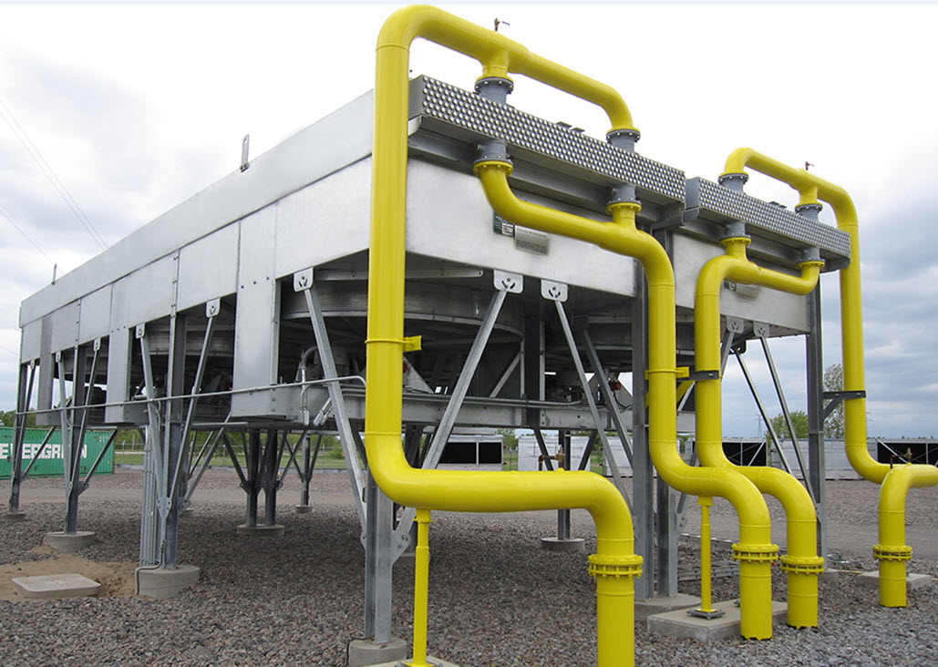
To insert a pump, select the desired node and use the menu option: Insert > Equipment > Air Cooler Nozzle API 661/ISO 13706
 button